Mastering CNC Press Brake Forming

FROM ADH blog
Publish Date: December 3, 2025
Ⅰ. Core Knowledge Module: Deconstructing the Logic Behind “Industrial Origami”
If we think of sheet metal fabrication as a form of modern industrial art, then press brake forming is undoubtedly its most sophisticated “industrial origami.” It’s not just about changing the shape of metal; it’s about re-engineering its physical properties. To truly master this technology, we must move beyond the shallow idea of “just bending a plate” and dive into the underlying mechanics and materials science that govern the process. For readers who want to connect these principles with actual shop-floor equipment, studying how an Electro-hydro CNC Press Brake integrates force control, crowning, and automation is an excellent next step.
1.1 Definition and Essence: Crossing the Boundary Between Elasticity and Plasticity
From a physics standpoint, press brake forming is a process that uses mechanical force to induce controlled plastic deformation in metal sheets. In essence, it is a subtle, highly controlled mechanical contest taking place inside the material itself.
As the punch moves downward, the sheet metal experiences intense internal stress changes. This process must be precisely controlled between two critical physical thresholds:
Exceeding the Yield Point: The applied force must surpass the material’s elastic limit, forcing the crystal lattice of the metal to slip so that it enters the plastic deformation zone. If the pressure is insufficient, the material behaves like a spring—deforming elastically and returning to its original shape once the external force is removed.
Stopping Short of Tensile Strength: The deformation must remain strictly within the range that avoids fracture. Once the material’s tensile strength is exceeded, microscopic cracks will begin to form and can quickly develop into complete failure.
One of the most fascinating yet troublesome phenomena in this process is the neutral axis shift. When the sheet is bent, the inner surface is subjected to strong compressive stress, while the outer surface experiences strong tensile stress. Only a thin internal layer—called the neutral axis—is neither stretched nor compressed. As the bend angle increases, this neutral axis will, counterintuitively, shift from the geometric center toward the inner radius of the bend. This change in material behavior is the fundamental reason why flat pattern calculations (K-factor) often deviate from theoretical values.
In addition, springback is the constant companion of bending. When the external force is removed, the residual elastic stress within the material tries to relax, partially opening the bend angle. Advanced bending practice is essentially a game of accurately predicting and compensating for this springback, something modern Electro-hydro CNC Press Brake systems increasingly handle with built‑in sensors and intelligent control.
1.2 Industrial Value: Why Is It the “Heart” of Modern Sheet Metal Fabrication?
Once laser cutting has solved the “profile” problem, it is the press brake that solves “dimension” and “rigidity.” Bending is the key step that turns a 2D flat sheet into a 3D structural component, and it is often described as the “heart” of sheet metal fabrication. Its core value is reflected in three dimensions:
From Flat to 3D: A Dimensional Leap: Whether it’s a precision electronics enclosure or a large architectural facade, bending gives flat material its spatial form. It is not only about shaping, but also about enabling function.
Geometric Multiplication of Structural Rigidity: By adding ribs or changing the cross-sectional shape (for example, turning a flat plate into a U-profile or channel section), the material’s moment of inertia increases dramatically. This allows us to achieve high structural strength using thinner, lighter material—perfectly aligned with the modern manufacturing trend toward lightweight design.
A Revolution in Manufacturing Efficiency: Bending technology greatly reduces the need for welding and mechanical assembly. A box that once required multiple plates to be welded together can now be produced in one piece using “notch-and-bend” techniques. This not only boosts productivity but also eliminates weld-induced thermal deformation and visible weld defects.
1.3 The Three Key Elements Model
Achieving a perfect bend cannot rely on experience alone; it requires a systematic mental framework. Every successful bend is the result of a dynamic balance between three core factors—what we can call the “golden triangle” of bending:
The Machine: The source of force and precision. Modern press brakes are no longer simple hydraulic rams. They integrate precision linear scales, dynamic hydraulic crowning, and in some cases full electric servo drives with robotic automation. Their mission is to deliver micron-level control of ram position (Y-axis) and stable force output. When comparing different machine architectures, referring to OEM brochures and case studies helps align capabilities with your own product mix and tolerance requirements.
The Tooling: The soul of the forming process. The upper tool (punch) defines the inside bend radius (IR), while the V-opening of the lower die determines the required tonnage and workable thickness range. Tool hardness (for example, laser-hardened 42CrMo4 steel) directly dictates whether the punch and die can maintain their geometric accuracy over tens of thousands of high-load cycles.
The Material: The biggest variable in the system. Differences between batches in thickness tolerance, tensile strength, or even rolling direction (grain direction) will all influence the final angle. In high-precision bending, the main challenge is often how to use algorithms and sensors to continuously compensate for the material’s inherent unpredictability.
Once you grasp the interdependent relationships among these three elements, you effectively hold the key to solving most bending challenges. In the following sections, we’ll dive deeper into how they work together to transform a cold steel sheet—through the “magic” of math and physics—into a precise industrial component.
Ⅱ. Mechanism Module: Mastering the Physics of Metal Deformation
If the hardware is the body of the bending process, then the underlying physics is its soul. Modern bending has moved far beyond the old “more force, better results” mindset. It is now a finely tuned balance among force, precision, and material properties. To truly command a press brake, you must first understand how metal flows between yield and fracture.
2.1 The Strategic Trade-Off Among Three Core Bending Methods
On the shop floor, the first strategic decision an operator must make is the choice of bending method. This is not just a matter of habit; it is a three-way trade-off between flexibility, accuracy, and machine life.
Air Bending: The “King of Flexibility” in Modern Industry Currently, air bending accounts for over 90% of all CNC press brake applications. Its core mechanism is three-point contact: the sheet touches only the punch tip and the two shoulders of the lower die, while remaining completely unsupported at the bottom of the V-opening.
Operating Principle: The bend angle is determined entirely by the punch penetration depth (Y-axis position). This means that with a single set of 30° sharp tooling, you can produce any angle between approximately 30° and 179° by simply adjusting the depth of stroke.
Industrial Value: This “angle by depth” logic dramatically reduces tool changes, making it ideal for high-mix, low-volume production. However, it demands extremely high Y-axis repeatability from the press brake—an error of just a few microns in depth can be geometrically magnified into a noticeable angle deviation.
Bottoming: A Misunderstood “Wall-Hugging Tactic” This is a concept that’s often misunderstood. Many assume “bottoming” means pressing the sheet all the way down to the very bottom of the V-opening. In reality, it refers to using pressure to force the sheet into full contact with the angled sidewalls of the V-die.
Locking in Accuracy: At this point, the bend angle is no longer governed by the machine’s stroke depth but is instead “copied” directly from the die angle. To compensate for springback, a 90° finished angle is typically produced with an 88° die, deliberately leaving about 2° of springback allowance.
Cost vs. Benefit: This method delivers exceptionally consistent angles, but the trade-off is steep: tonnage requirements soar to 3–5 times that of air bending, and you lose angle flexibility—one die can only produce one fixed angle.
Coining: The Violent Aesthetics of Metal Flow This is both the oldest and the most extreme bending process. The punch doesn’t just bend the sheet; it drives pressure to 5–10 times that of air bending and pushes through the neutral axis, forcing intense plastic flow of the metal and actually thinning the material in the bend zone.
Physical Significance: Such enormous pressure completely erases the elastic “memory” of the metal lattice, creating the physical phenomenon often described as “zero springback.”
Application Limits: Because it inflicts severe wear and fatigue on both the machine and tooling, coining is now reserved for ultra-thin sheets or niche cases where the radius tolerance is extremely tight (for example, precision electronic springs).
2.2 The Critical Physical and Mathematical Models
When you are competing at the micrometer level, rules of thumb have to give way to rigorous mathematical models. Only by understanding the physics behind the formulas can you accurately predict and control the final formed shape.
Neutral Axis Shift and the K-Factor Paradox
When metal bends, the inside is compressed and thickens, the outside is stretched and thins, and only the central “neutral axis” keeps its length. As the bend radius shrinks, the compressed material on the inside has nowhere to go and forces the neutral axis to shift inward toward the inside radius. This is the physical essence of the K-factor (K = t/T). Here we encounter a counterintuitive “hardness paradox”: we usually think harder materials are more difficult to bend, yet data show that the harder the material (such as stainless steel), the higher its resistance to compression, and the more the neutral axis is pushed inward. As a result, stainless steel typically has a lower K-factor (around 0.33) than soft aluminum (around 0.5). Grasping this is crucial for accurately calculating flat patterns.
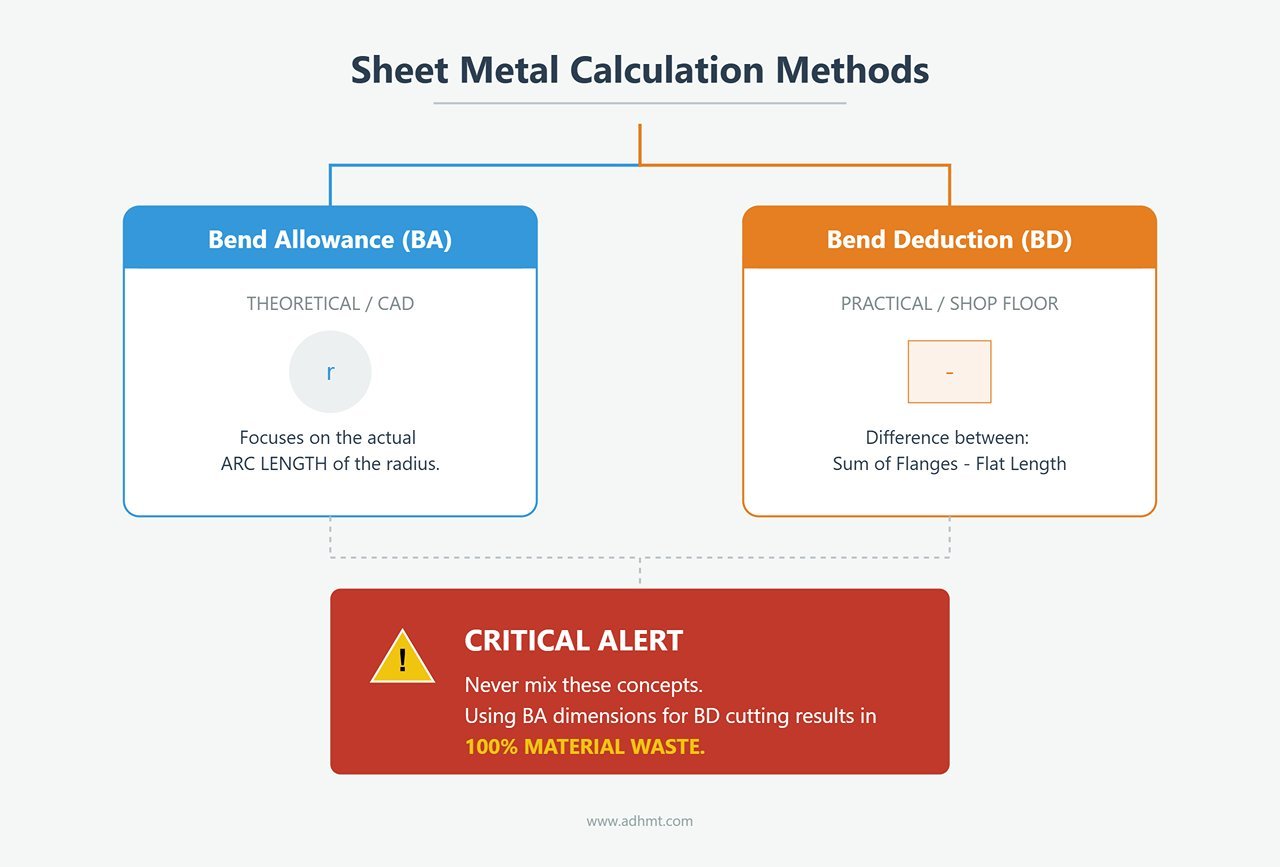
Flat-Pattern Calculation: The Life-or-Death Choice Between BA and BD
This is where beginners most easily “crash and burn.” Both methods aim to find the blank length, but their mathematical logic is fundamentally different:
Bend Allowance (BA): Focuses on the actual arc length of the bend radius. This is the core calculation method used inside CAD systems such as SolidWorks.
Bend Deduction (BD): The shop-floor veteran’s practical approach. It is defined as the difference between the sum of the two outside flange lengths and the final flat length.
Practical Warning: Never mix these two concepts. If your drawing is dimensioned and calculated using BA, but the operator cuts blanks based on BD-style empirical values, your scrap rate will be 100%.
Springback: The Inescapable “Elastic Ghost”
The moment the load is removed, residual elastic stress inside the metal tries to open the bend angle. Gardiner’s Formula reveals the variables behind this behavior: springback is directly proportional to the material’s yield strength and inversely proportional to its Young’s modulus (stiffness). Even more important is the R/T ratio rule: when the bend radius (R) is much larger than the sheet thickness (T)—that is, for large-radius bends—plastic deformation is insufficient, and springback increases exponentially. This is the fundamental physical reason why roll forming large radii is far harder to control precisely than making sharp bends.
Ⅲ. Hardware Ecosystem: The Foundation of a High-Performance Production System
If physics is the soul of bending, the hardware system is the body that carries that soul. In modern high-precision manufacturing, a press brake is no longer just a hydraulic jack; it is a tightly integrated ecosystem of drive units, tool matrices, and compensation systems. Understanding each element of this ecosystem is the prerequisite for building stable, repeatable production capability.
3.1 Evolution and Selection of Drive Technologies
The heart of any press brake is its drive system. Over the past two decades, drive technology has undergone a revolution from brute force to intelligent control. The drive type you choose directly determines your plant’s energy consumption, maintenance intervals, and ultimate precision ceiling.
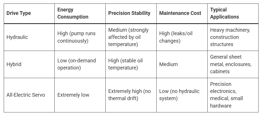
Hydraulic Drive – The Traditional Power Beast
This is the classic architecture, using a high-flow hydraulic pump running continuously to provide pressure.
Advantages: No practical upper limit on tonnage; ideal for thick plate and heavy industry; lowest initial equipment cost.
Pain Points: A textbook high-energy-consumption solution. The pump runs whether you are bending or not. Even worse is thermal drift: as the machine runs, oil temperature rises and viscosity drops, causing micrometer-level drift in the ram’s bottom dead center. This directly undermines angle stability and forces frequent re-calibration.
Hybrid / Servo-Hydraulic Drive – The Sweet Spot of Efficiency and Precision
Currently the mainstream market choice and often the best value. Its core concept is “on-demand oil supply”: the servo motor only drives the pump while the ram is moving down and remains still in standby.
Core Value: Cuts energy consumption by more than 70% compared with pure hydraulic systems and maintains excellent oil temperature control, effectively eliminating thermal drift.
Response Speed: Millisecond-level servo response allows ram approach speeds above 200 mm/s, dramatically reducing non-productive travel time.
All-Electric Servo Drive – The Precision Dancer for Clean Environments
This design eliminates hydraulic oil entirely. Servo motors, combined with precision ball screws or belt-and-pulley systems, drive the ram directly.
Extreme Precision: Ram repeatability can reach an astonishing ±0.001 mm.
Application Scenarios: With no risk of hydraulic oil contamination, this is the technology of choice for medical devices, precision electronics, and high-end kitchenware. However, the mechanical structure limits load capacity, so tonnage is typically capped at around 300 tons.
3.2 Tooling Systems: Configuration Logic for Punches and Dies
Tooling is the medium through which the machine “talks” to the metal. Many factories invest in million-level press brakes but then pair them with poor-quality tools, dooming the final product to mediocrity. High-end bending tools must strike a perfect metallurgical balance between hardness and toughness.
The King of Tool Steels: 42CrMo4 (Chrome-Moly Alloy Steel)
Standard C45 steel simply cannot withstand the extreme loads of modern bending. For top-tier tooling, the industry benchmark is 42CrMo4. With an exceptionally high tensile strength (around 1000 MPa), it ensures the tool resists chipping and plastic deformation even under very high tonnage.Laser Hardening: A Game-Changer in Heat Treatment
Conventional induction hardening often makes the entire tool brittle. High-end modern tooling instead uses laser surface hardening, selectively hardening only the stressed areas—the punch radius (R) and die shoulder around the V-opening—to 56–60 HRC to a depth of 2–3 mm, while the tool body retains good toughness. This “hard outside, tough inside” structure is the key to achieving tool life beyond 100,000 bends.Mark-Free Tooling and Surface Protection Strategies
When processing visible parts in aluminum or stainless steel, friction on the die shoulders can leave unsightly pressure marks.Roller Dies: Replace the fixed V-die shoulders with rotating rollers to convert sliding friction into rolling friction, eliminating indentation at the physical source.
Polyurethane Protection Film: Place a 0.4–0.6 mm high-strength polyurethane film on top of a standard V-die. Despite its low cost, it is a highly effective solution for preventing surface scratching.
3.3 Accuracy Assurance System: The Overlooked Core Components
When the ram applies hundreds of tons of force, physics dictates that the machine’s beam and bed will undergo slight elastic deflection (bulging in the center). Without compensation, the bent part will show the “canoe effect”—a larger angle in the middle and smaller angles at both ends.
Deflection Compensation (Crowning): The Ultimate Weapon Against Deformation
Mechanical Crowning: Represented by technologies such as Wila’s. Inside the bed, two sets of precision wave-shaped wedges slide against each other to generate a convex curve that closely matches the ram’s deflection profile. This is currently the most accurate compensation method and allows for fine local adjustment.
Hydraulic Crowning: A series of hydraulic cylinders mounted under the bed push up to compensate deflection. While it delivers strong force, its response speed and curve-matching accuracy are generally inferior to mechanical systems.
Expert Recommendation: For press brakes with a working length over 2.5 meters, deflection compensation is a “must-have” rather than an optional feature.
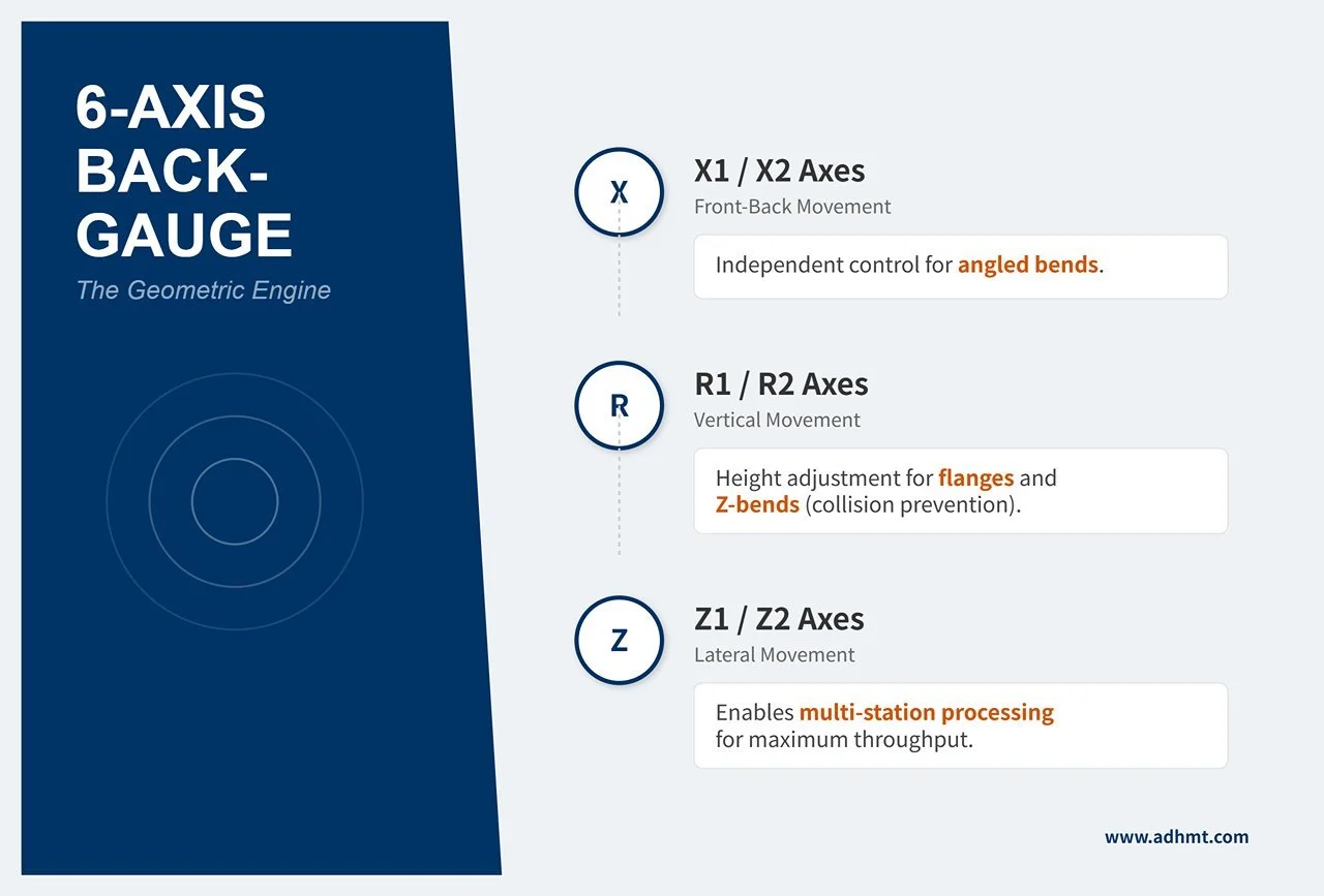
6-Axis Backgauge: The Spatial Positioning Reference
Do not think of the backgauge as just a simple stop plate. A modern multi-axis backgauge is the geometric engine that enables complex part forming:X1/X2 Axes: Independently control the front–back position on the left and right, making it easy to handle angled bends.
R1/R2 Axes: Independently control vertical height, which is critical for preventing collisions when forming flanges and Z-shaped bends.
Z1/Z2 Axes: Control left–right movement. Combined with segmented tooling, they enable multi-station continuous processing (for example, sharp bends on the left, hemming on the right), dramatically increasing throughput.
Once you understand the underlying logic of this hardware ecosystem, you are no longer a passive machine operator—you become a process expert capable of fully leveraging a high-performance system. With this solid foundation in place, hands-on production work becomes far more controlled and efficient.
Ⅳ. Advanced Optimization Module: Expert Strategies for Cost and Efficiency
When equipment performance has been pushed to its limits and your understanding of the principles is highly refined, the next profit frontier lies in process optimization and extreme efficiency. This is the critical leap that transforms a traditional “blacksmith’s workshop” into a modern “smart factory.” In this module, we explore how advanced techniques and management strategies can significantly increase output and yield without additional capital investment in machinery.
4.1 Advanced Techniques for Complex Bending Scenarios
True master-level bending is not just about producing standard parts—it is about solving non-standard challenges using standard tooling. Do not let your imagination be constrained by the tools on hand; complex geometries are often achievable through clever process decomposition.
Forming Large Radii with Step Bending (Bump Bending / Step Bending)
Core Concept: When the drawing specifies a large radius, such as R = 200mm, and you do not have an expensive dedicated radius die, you can use the CNC system’s algorithms to approximate the curve by splitting it into dozens of tiny straight bends.
Algorithm Guidelines:
Pitch: The distance between two successive bends. Expert practice recommends setting Pitch ≈V/2 (where V is the lower die opening).
Number of Steps N=(inside arc length/Pitch)
Consistency is Critical: Each bend must have exactly the same angle and depth. Any variation will produce a visible “polygon” effect on the radius. Modern CNC systems can automatically calculate the backgauge position (X-axis) and ram depth (Y-axis) for every step; the operator’s main task is to feed the sheet smoothly and consistently.
Deep Box Bending and Interference Avoidance
Pain Point Scenario: When bending the third and fourth sides of a rectangular box, the already-formed flanges on the first two sides are very likely to collide with the ram or upper tooling, making the part impossible to process.
Solution Matrix:
Machine Selection: Prioritize models with greater throat depth and daylight opening.
Tooling Strategy: Use extension holders together with gooseneck punches. The gooseneck’s recessed profile provides clearance for already bent flanges.
Verification Formula: Maximum bend height < (machine daylight − total tool height − safety clearance).
Forming Closed Profiles
Challenge: After the final bend, the workpiece completely encloses the upper punch, trapping the tool inside so it cannot be removed.
Breakthrough Techniques:
Segmented Punches: Use a “left-right segmented” punch arrangement (for example, 100 mm sections at each end with a gap in the middle). After bending, slide the end segments toward the center to create clearance and remove the part easily.
Special Tool Paths: For particularly challenging shapes, first bend the sheet into a “U” profile, then use a horn tool or a side-action bending machine for the final closing operation.
4.2 The Efficiency and Cost Optimization Matrix
In sheet metal fabrication, the electricity cost while the machine is running is easy to quantify—but the hidden cost of downtime during tool changeovers is often the real profit killer.
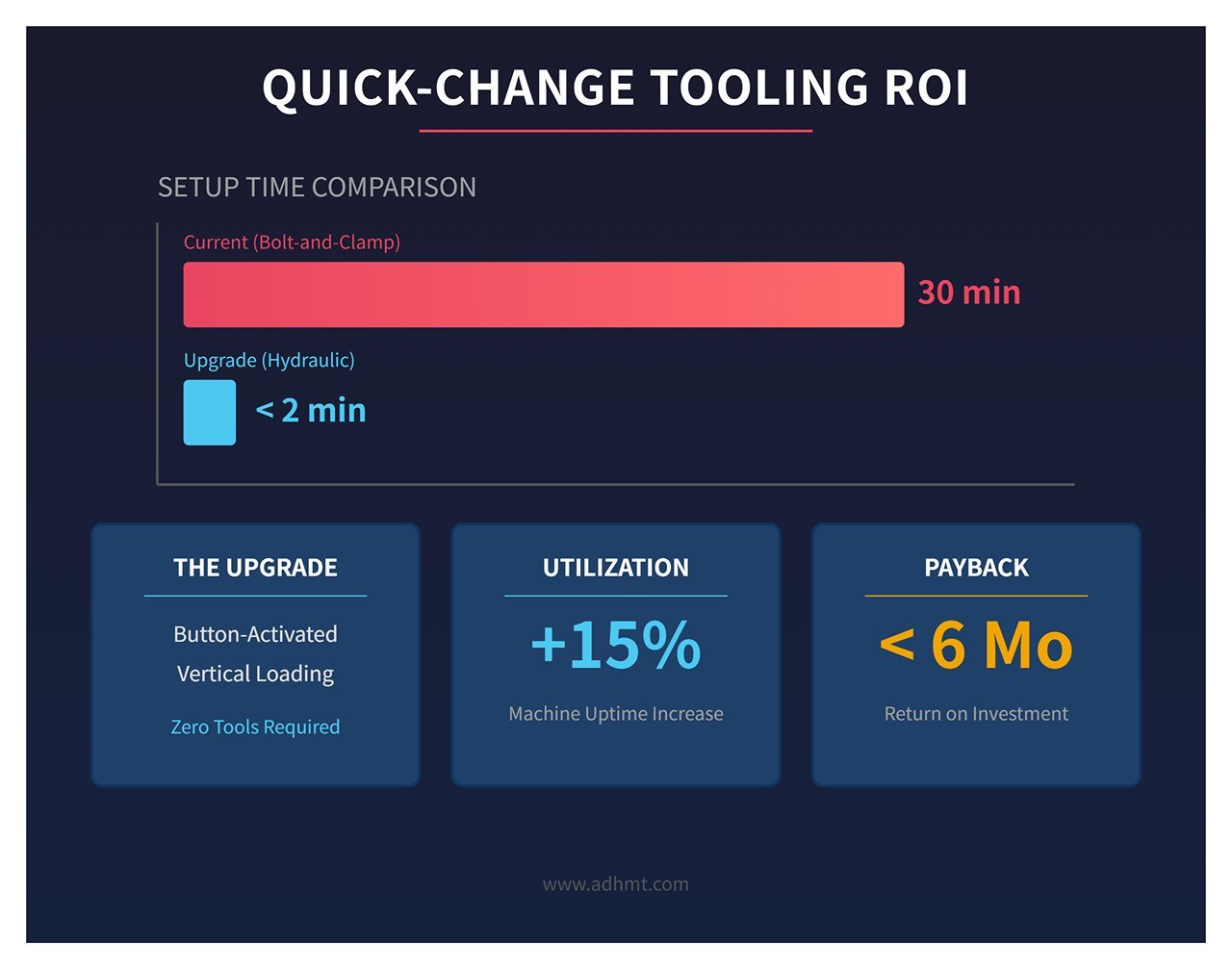
ROI analysis of quick-change tooling systems (Quick Clamp)
Current state: With conventional bolt-and-clamp style tool changes, replacing a full-length tool set typically takes 20–30 minutes and often leads to tool damage due to uneven clamping force.
Upgrade benefits:
Hydraulic/pneumatic clamping: Button-activated systems from brands like Wila or Trumpf allow vertical loading and unloading of tools with a single press. Hydraulic pins retract automatically, and the entire process takes less than 2 minutes.
Benefit calculation: For a High-Mix, Low-Volume (HMLV) production model, this upgrade can directly increase effective machine utilization by more than 15%, typically paying back the retrofit cost within six months.
Group Technology: a management revolution
Strategy shift: Move away from the traditional “first-come, first-served by order” scheduling mindset and switch to scheduling based on shared tooling requirements.
Implementation: Group all orders that require a V=12 mm die (regardless of customer) into the morning shift, and all orders requiring V=24 mm into the afternoon.
Data-backed results: This approach can reduce tool changeovers by an average of 80%, significantly lowering dependence on highly skilled setup technicians.
Sheet followers: a double dividend
Pain point: When processing large sheets over 2 meters, the traditional approach requires 2–3 operators to support the material. Any mismatch between their lifting speed and the ram’s movement can easily cause “reverse bends” or sagging deformation from gravity.
Automation solution: Equip the press brake with mechanically synchronized follower arms that move in perfect sync with the ram.
Benefits:
Labor savings: Immediately reduces the need for 1–2 assistants.
Quality improvement: Eliminates angle deviations and surface scratches caused by manual handling.
4.3 Digitalization and Software-Driven Performance
In the era of Industry 4.0, a press brake’s core competitiveness is no longer just the thrust of its hydraulic system, but the computing power of its “brain” – the software.
Offline programming: driving trial-and-error costs to zero
Workflow redesign: Completely abandon the outdated model where operators stand at the machine with a drawing, tweaking programs by trial and error. Today, process engineers perform full-fidelity simulations in the office using software such as AutoPol, Radbend, or BySoft.
Core capabilities:
Collision detection: Potential issues like “the third bend will hit the backgauge” or “the part will interfere with the machine frame” are identified on-screen, allowing the bend sequence to be corrected in advance.
Automatic tooling setup: Based on part geometry, the software automatically recommends the optimal tool combination and station layout (setup plan).
Value: Effective machining time (Green Light Time) can be increased from an industry average of around 40% to over 75%.
Real-time angle correction
Closed-loop control: Systems such as LazerSafe IRIS or built-in contact probes measure the bend angle in real time during the forming process.
First-piece-as-good-part: If the system is set to 90° but the probe reads only 89.5° after material springback, the ram automatically makes a second, fine correction of 0.5°. This virtually eliminates scrap caused by batch-to-batch variation in material hardness or thickness and delivers true “zero-defect manufacturing.”
Ⅴ. Industry Applications and Outlook: The Future Landscape of Bending Technology
Looking back from the threshold of Industry 4.0, press brake forming has evolved from pure “mechanical force” into a symphony of data and automation. This technology not only underpins the skeleton of modern industry but continually pushes the boundaries of what can be manufactured. From pressure-resistant housings for deep-sea probes to precision shielding cans in smartphones, the application range of bending technology extends far beyond what most people imagine.
5.1 Typical Industry Solutions: From Superstructures to Semiconductors
Different industries face very different pain points in bending, which in turn has driven highly specialized solutions.
Aerospace: the quest for ultra-lightweight structures vs. titanium alloys
Challenge: Aerospace applications demand an extreme strength-to-weight ratio, leading to extensive use of titanium alloys (Ti-6Al-4V) and high-temperature nickel-based alloys. These materials have very high yield strength and highly unpredictable springback (often 15°–20°).
Solution: Processes must use hot bending or highly rigid machines with adaptive springback compensation. To avoid scrapping extremely expensive materials, 100% offline simulation and in-process laser angle inspection are typically mandatory.
Architectural facades and construction machinery: the challenge of extra-long parts
Challenge: Aluminum facade panels for skyscrapers and crane booms often reach lengths of 6 meters or even 12 meters. At these lengths, sheet sag due to gravity and machine deflection can be fatal to part quality.
Solution: Tandem press brakes are the standard setup—two machines are CNC-synchronized to run as a single system. Combined with fully automatic sheet follower arms, this configuration overcomes the limits of manual support and ensures straightness along the entire bend line.
Precision electronics and medical devices: cleanliness and miniaturization
Challenge: Parts like pacemaker housings or heat sinks in 5G communication modules can be as small as 10 mm, and any hydraulic oil contamination is strictly prohibited.
Solution: All-electric servo press brakes dominate this field. Their oil-free design meets cleanroom standards, and their very high ram acceleration (up to 2.0 G) satisfies the electronics industry’s demand for cycle times measured in seconds.
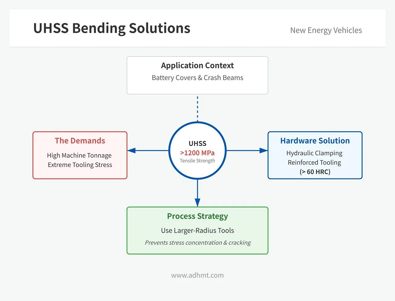
New energy vehicles: safety through ultra-high-strength steel
Challenge: Battery covers and crash beams increasingly use ultra-high-strength steels (UHSS) with tensile strengths above 1200 MPa, posing severe demands on both tooling and machine tonnage.
Solution: Use heavy-duty hydraulic clamping systems together with reinforced tooling (hardness > 60 HRC). From a process standpoint, larger-radius tools are preferred to avoid stress concentrations and cracking at the bend in high-strength steels.
5.2 Smart Bending in the Industry 4.0 Era: From Human–Machine Dialog to Digital Twins
In the bending shop of the future, operators will shift from “manual laborers” to “system supervisors.” Intelligence and automation will reshape every step of the process.
Robotic Bending Cells
More than just a robot arm: Real automation is not simply adding a manipulator. It’s the integration of a 7‑axis robot + automatic tool-change library + vision-based alignment system. Beyond tirelessly handling heavy parts, the robot uses torque sensors to detect tiny material tolerances and automatically adjusts its posture. This makes true lights‑out manufacturing possible—running overnight with no operators on site while still consistently producing in‑spec parts.
Augmented Reality (AR) Assisted Operation
A revolution in work instructions: Using devices like Microsoft HoloLens or the machine’s built‑in projection system, drawings, tool locations, and bending sequences are directly projected onto the workpiece and the machine. Operators no longer need to look down at paper drawings. Green light guides say “place the part here next,” while red warnings highlight “keep hands clear.” This dramatically reduces dependence on highly experienced operators and enables new hires to get up to speed much faster.
Data‑Driven Process Optimization (AI & Big Data)
A cloud‑based brain: Modern machines are connected to the cloud, continuously collecting springback data for a wide range of materials. When you run a new batch of 304 stainless steel, the system taps into a global database of millions of bending operations and advises you: “Based on this batch number, we recommend increasing dwell time by 0.2 seconds.” This kind of big‑data‑driven self‑improvement is the core moat of intelligent manufacturing.
5.3 Summary & Call to Action: Your Key to the “Beauty of Manufacturing”
Press brake forming may look like a rough, brute‑force process, but it is in fact one of the most technically sophisticated stages in precision manufacturing. It blends the depth of metal physics, the rigor of mechanical engineering, and the intelligence of modern algorithms.
To the manufacturing masters of tomorrow:
Respect the fundamentals: You can always buy top‑of‑the‑line equipment, but a solid grasp of the underlying physics—yield strength, springback, neutral‑axis shift, and more—is the real inner strength you need to solve tough, complex problems.
Embrace software: The real battlefield of the future is less on the shop floor and more in the office. Those who master offline programming and digital production scheduling will outclass their competitors in both cost and efficiency.
Keep evolving: Technology is advancing at breakneck speed, from all‑hydraulic to full electric‑servo systems, from manual trial‑and‑error to AI‑driven adaptive control. Stay sensitive to new technologies—don’t let your hard‑won experience turn into chains that limit your thinking.
This guide is more than an operating manual; it’s a roadmap to advanced manufacturing. Now, armed with a deep understanding of the “golden triangle,” go review your next drawing and refine your next bending operation. Let every cold sheet of metal in your hands reflect the brilliance of industrial civilization with precision and purpose.
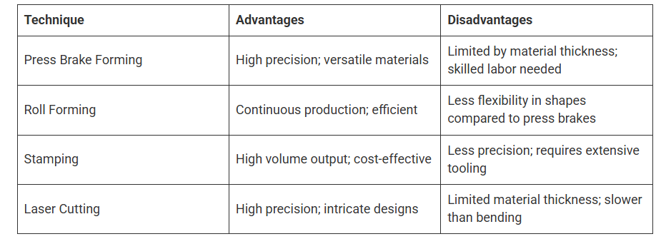
Ⅵ. Comparison with Other Metal Forming Techniques
Ⅶ. FAQs
1. What is the purpose of a press brake?
A press brake is a piece of manufacturing equipment that is used to bend sheet metal. It is typically narrow and long so that large pieces of sheet metal can be bent by it. Press brakes perform these bends by clamping the sheet or plate between the movable punch and the stationary die.
2. Can press brake forming be used for large-scale production?
Yes, press brake forming can be effectively used for large-scale production, particularly when utilizing CNC press brakes. CNC press brakes provide high precision, repeatability, and efficiency, making them well-suited for high-volume manufacturing.
They can be programmed to execute complex bending sequences with minimal operator intervention, significantly reducing cycle times and labor costs. Additionally, advancements in automation technology, such as robotic material handling and automated tool changers, further enhance the capability of press brakes to handle large-scale production tasks effectively. For plants evaluating such an upgrade path, reviewing CNC press brake brochures and then contact us for an application-specific assessment can help de-risk investment decisions.